
Serial adapter for 3.3V TTL
Introduction
This document describes how to build a converter from 3.3V TTL levels to RS232, which allows interfacing to a standard PC 9-pin D-sub port.
Bill of materials (BOM)
To build the serial adapter you will need the following parts:
- 1 x piece of solderable breadboard, predrilled with standard 0.1" spacing
- 1 x MAX3232 dual driver/receiver
- 1 x 16 pin DIL socket (optional)
- 5 x 0.1uF/10V polarized capacitors
- 1 x 9 pin D-SUB male connector
- up to four connectors for the serial header in your NAS box
- some wire
In this description I am using a board where stripes of three holes are connected with copper. To connect to the NAS serial port I have glued together two header plugs with three holes each, forming a connector for a 2x3 serial header, suitable for Synology and QNAP. Depending on the kind of serial header in your NAS box you will have to build a suitable plug.
Schematic
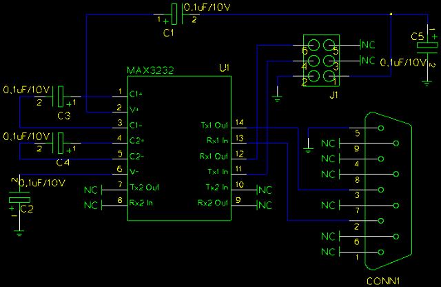
This is the converter circuit we have to build, drawn using
gschem from the
gEDA suite.
-
J1is the plug for the serial header. Pin 1 is 3.3V, pin 2 isGND, pin 4 isTX. and pin 6 isRX. Adapt this to your NAS as required. -
U1is the MAX3232. Note that pin 15 (GND) and pin 16 (VCC, 3.3V) are not visible, but have to be connected nevertheless. -
CONN1is the male D-SUB interface with 9 pins, where pin 2 isRX, pin 3 isTXand pin 5 isGND. -
The five capacitors are called
C1toC5.
Soldering
The following picture shows the soldering side of the board, to give you an idea how to place the components and which copper stripes have to be connected.
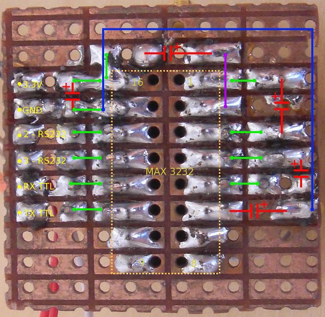
- Red: The positions of the five polarized capacitors. Watch their polarity!
- Green: The arrows show which copper stripes have to be connected. You can do that either with small wires on the component side or with a soldering bridge on this side.
-
Violet: A short wire on the component side to
connect pin 2 of
U1with the positive side ofC1. -
Blue: A longer wire on the component side to
connect
C2atU1pin 6 withGND. -
Yellow: Here you will solder seven long wires.
Three of them (
2 RS232,3 RS232andGND) connect to the D-SUB RS232 interface while the other four are for the serial header in the NAS. Note that one hole (labeledGND) is used for both and gets two wires.
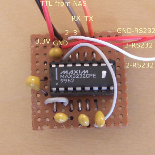
This is how the component side of the finished serial adapter looks like:
Back to NetBSD/sandpoint Port Page